Introduction to Transactive Energy and TESP
What Is Transactive Energy?
Let’s start from the beginning: what is transactive energy? Though there are many definitions the one we’ll use here comes from the GridWise Architecture Council [24]
A system of economic and control mechanisms that allows the dynamic balance of supply and demand across the entire electrical infrastructure using value as a key operational parameter.
Transactive energy seeks to allow all actors in the electrical energy system to participate in the dynamic management of the power system, most fundamentally, the moment-by-moment balancing of supply of electrical energy and its demand. Typically, the balancing is done by only the largest actors in the system: the large bulk power system generators and their customers, the utility companies (sometimes with the help of an intermediary market and system manager). These interactions take on various forms from long-term contracts to auctions every few minutes and effectively form the wholesale electricity market.
Most end users of that energy, though, are not part of this interaction and are generally ignorant of it. We may experience some efforts by our local utility to include us through time-of-use tariffs where the price of energy changes in predictable ways throughout the day or by peak-period pricing where the cost of energy rises dramatically for a few hours a few times a year. These kinds of mechanisms are muted attempts to incentivize energy customers of the state of the power system with higher retail prices intended to follow the general trend of wholesale prices. But because these retail tariffs are pre-defined once and used for years to come, they have no ability to accurately reflect the state of the power system on any given day.
Transactive energy seeks to change that by including all actors, including the end customers, in the management of the power system by providing appropriate value signals to all participants such that the dynamic needs of the power system can be addressed appropriately by all participants. If electrical energy is in short supply, a higher price to customers can incentivize them to reduce consumption until further resources can be provisioned or the peak in demand has passed. Conversely, when prices are low, consumers are signaled that energy-intensive activities (e.g. charging electric vehicles, running pool pumps) will be less costly and will not place an undue stress on the power system.
By choosing to enable all participants in the management through appropriate value signals, transactive energy hopes to use the flexibility in all existing actors behavior to manage the power system in a more efficient manner
Transactive Energy Simulation Platform (TESP)
Traditionally, analysis of power systems has been split cleanly between the bulk power system (e.g. long-distance transmission lines connecting large generation to large load centers like cities) and the distribution system (e.g. neighborhoods). This separation has been motivated by different needs. The bulk power system is often concerned with finding the most economical means of dispatching generators to meet the expected load or trying to determine the most economical expansion of the power system. Distribution system planners have been concerned with appropriately sizing the power lines the run through a neighborhood or what measures need to be made to ensure good voltage management.
Transactive energy, by trying to include all actors as participants in the management of the system, necessarily breaks down these analysis barriers and ties these two distinct analysis domains togethers. For appropriate analysis of a transactive system, the analysis needs to allow participation of the management of the system by all actors which means the analysis tools need to be able to represent all actors in appropriate ways. Furthermore, the models of the participants need to be more fully fleshed out so that large loads (e.g. air conditioners, EV chargers, water heaters) can be modeled in way that allows their loadshape to be altered as actors respond to value signals. And depending on the particular analysis, further models that were not previously used may be needed such as those or rooftop solar panels or community energy storage.
Given these more complex analysis requirements, a more complex simulation technique was needed: co-simulation. Co-simulation allows the dynamic integration of multiple simulation tools such that the outputs of each can can be used as inputs to others. For example, the voltage at a particular transmission bus that is found when the power flow is solved for the bulk power system can be used as the substation voltage when the distribution system needs to solve its power flow. Conversely, the distribution system load can be fed back up to the bulk power system simulation for use when it solves it’s power flow.
Co-simulation allows the analysis of more complex and larger scale power system problems than would be possible otherwise but comes with the cost of complexity. The individual simulation tools used in the co-simulation need to integrated into the co-simulation platform so they can send and receive messages with other tools. Each tool needs to be configured to not only use the appropriate models but also to send and receive the correct messages. The data coming out of all the simulation tools needs to be synthesized and analyzed to form conclusions.
The Transactive Energy Simulation Platform (TESP) has been developed by Pacific Northwest National Laboratory (PNNL) under funding and direction by the United States Department of Energy to minimize the barriers of transactive energy analysis (the complexities of co-simulation being chief among them) to allow for more efficient and effective analysis of potential transactive energy schemes. Specifically, TESP aims to provide:
Appropriate simulation tools to model common transactive scenarios
Integrated simulation tools into a co-simulation platform
Generic models and other input datasets that may be needed for transactive analysis.
Demonstrations of the various co-simulation capabilities
Fully realized examples of transactive analysis
All of the above in an easily managed software package that is readily customizable and altered for particular analysis needs.
TESP Software Stack Overview
Fig. 1 shows the typical co-simulation software stack when using TESP for TE analysis.
GridLAB-D covers the electric power distribution system [8] and residential buildings (OpenDSS is a similar alternative).
PYPOWER, MATPOWER/MOST or AMES covers the bulk power system and the transmission system operator (TSO) [1, 28].
EnergyPlus covers large commercial buildings [12]
ns-3 is a communication system simulator that can also host software agents.
The integrating message bus, using either the Hierarchical Engine for Large-scale Infrastructure Co-Simulation (HELICS [20]) manages the time step synchronization and message exchange among all of the federated simulation modules.
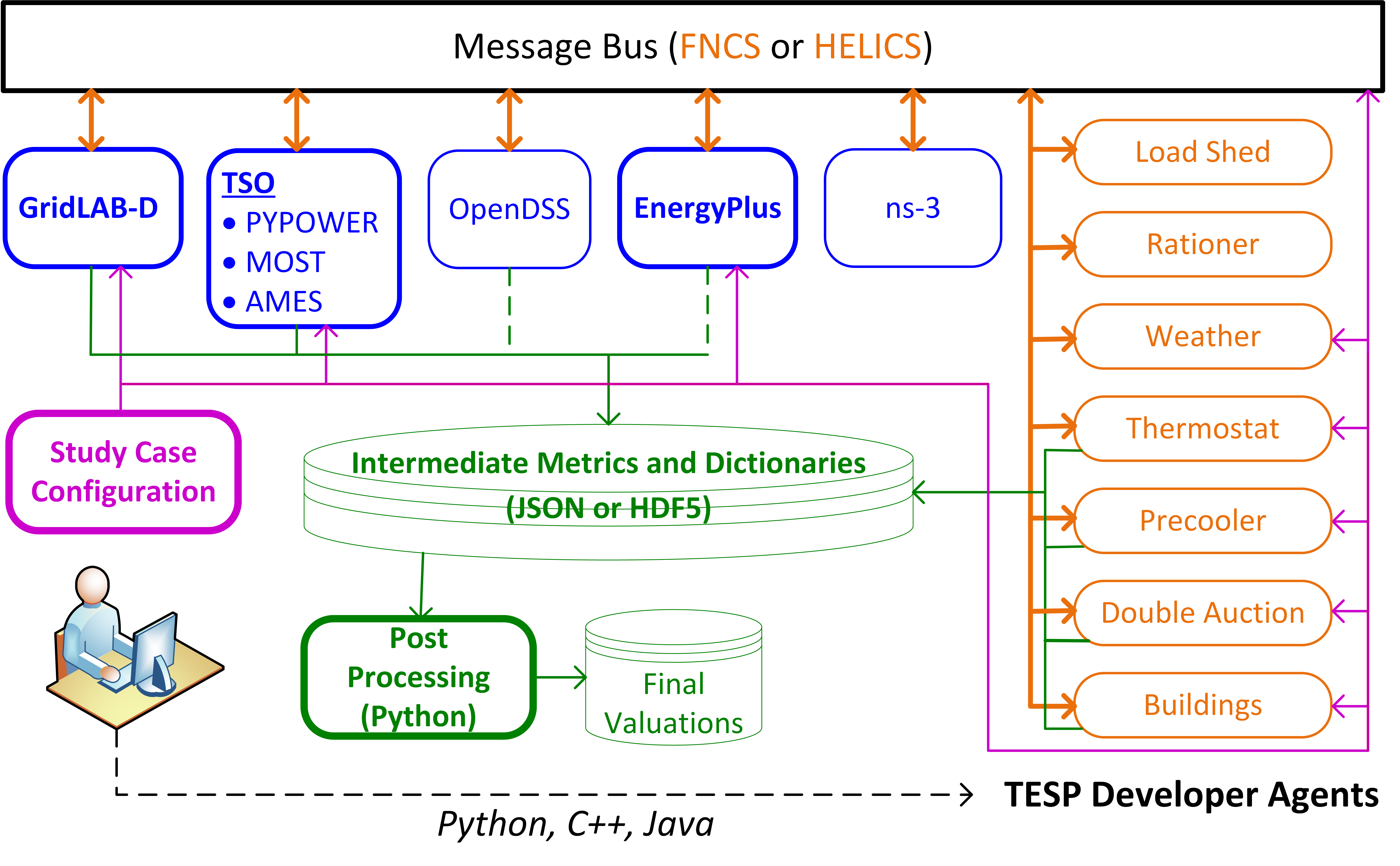
Fig. 1 TESP Rev 1 components federated through FNCS and/or HELICS.
Assuming this software stack satisfies the needs of the particular analysis, the user interacts with TESP by configuring simulation cases (magenta) and then running them. Simulation federates or Agents, write intermediate outputs and metadata (green), which the user plots, post-processes and analyzes to reach conclusions.
(Some of of the simulators and agents in Fig. 1 have to be configured by hand. OpenDSS writes output in its native, non-TESP format, and EnergyPlus writes output only through the Buildings agent; these are indicated with dashed green lines. The ns-3 simulator doesn’t write output; it’s presently used in just one example, for which the GridLAB-D outputs are adequate.)
Most of the Agents in Fig. 1 were implemented in the Python programming language, though custom code for TESP can also be implemented in other languages like C++ and Java. To demonstrate, the Buildings agent was implemented in C++ and one version of one of the examples distributed with TESP (Load Shed) has an agent was written in Java.
Overview of Transactive Energy Analysis Process
Given the complexity of many TE analysis and the variety of software components that may need to be used to perform said analysis, taking time to clearly plan the analysis conceptually and practically will generally save time in the long run. The following is an outline of the process PNNL has developed and implemented for TE Analysis.
Value Model
As TE is fundamentally built on the concept of value transactions or exchanges, developing a value model that explicitly shows this can be helpful. These models are able to clearly show which system actors will be modeled in the TE analysis, which ones are outside the system but involved in the value exchanges and which values are being exchanged through the operation of the TE system.
With the value exchanges modeled, it is much easier to identify and define relevant performance mechanisms for the TE system. Is an actor giving up comfort to save money (for example by adjusting a thermostat during a high-price period)? If so, defining a metric to measure how much discomfort the actor is enduring could be important. How far from the desired setpoint does the thermostat go? Are there times when a maximum or minimum setpoint is reached? And how much money does the actor save by responding to this dynamic price? These metrics will be the measure by which the TE system is evaluated and should be clearly related to the value model. Furthermore, generally, they should be able to be calculated in both the transactive case and the base or business-as-usual case. If this is not the case, it is likely a sign that the metrics have not been entirely thought through.
Finally, prior to writing any code, it is worth developing a flowchart or sequence diagram of how the TE system (or even all simulated activities) will operate. This flowchart helps provide clarity of how and when the value exchanges will take place and the process by which each actor accrues value. It will also serve as a good starting place when writing the code to realize the TE system.
An example of these models can be found in the Valuation Model.
Design of Analysis
With a value model in place and the fundamental of the TE system outlined, the question then becomes one of methods and means: what needs to be done to achieve the analysis goals? For TE studies, co-simulation will likely be a part of the answer but is likely to be far from complete. It would not be unusual for new input datasets to be needed by various entities in the co-simulation. There may be specific values that need to be defined either for the co-simulation (e.g. renewable penetration level) or for use in post-processing the data (e.g. assumed cost of solar panels in the year of the analysis).
Regardless, the critical element are the performance metrics that have been previously defined. These metrics define specific input data and the goal of the analysis is to produce those values. Some of these may come directly from the co-simulation but it would not be unusual for many of them to defined by separate analysis or from relevant literature. These data are used by a series of analysis steps, one after the other, to produce the required inputs for the final metrics. Develop a plan for this analysis workflow is helpful in not only ensuring that all the data that is needed has been accounted for but also helping to guide scoping decisions and being clear about where the extra effort may be needed to achieve the analysis goals.
To show the impact of the TE system, to demonstrate the impacts of the system the design should make it clear in some way what defines the base or business-as-usual case and what constitutes the transactive case(s). Keeping the system models and inputs constant across the cases makes a direct apples-to-apples comparison possible in the key performance metrics.
Lastly, in addition to the key performance metrics, there are likely to be supplemental data that is helpful in validating the performance of the co-simulation and the analysis as a whole. These validation metrics would not generally be defined by the value model because they generally are not tied to the value flows. For example, if the TE system adjusts air-conditioning thermostats higher during high price periods and lower as the price drops a validation graph could be created to show the thermostat setpoint throughout the day with the energy price overlayed. Though this graph and its associated data are not necessarily needed to calculate the final value-based metrics it is useful to confirm that the co-simulation that produced this data is working as expected.
An example of these models can be found in the Analysis Design Model.
Co-Simulation Implementation and Execution
With an analysis plan in place, now the direct work of implementation can begin. The analysis plan should clearly show the analysis steps that are required (e.g. writing new transactive agent code, finding input data sets, writing scripts for calculating final metrics).
The co-simulation will be run at some point and this may require computation resources beyond what a typical desktop or laptop computer provides. There may need to be some extra work done in developing deployment plans and tools for the co-simulation components. Relatedly, the datasets produced by the co-simulation could be very large and requires more complex data handling and storage techniques.
Post-Processing and Analysis
With the final dataset produced from all the necessary analysis steps the validation and key performance metrics can be calculated and reviewed. Ideally the presentations of the data show both that the co-simulation and the analysis as a whole have been constructed correctly (validation) and that the TE system is having the expected impact. Both the validation and the value-based metrics should have comparisons between base and transactive case(s) making the impact of the transactive system clear.